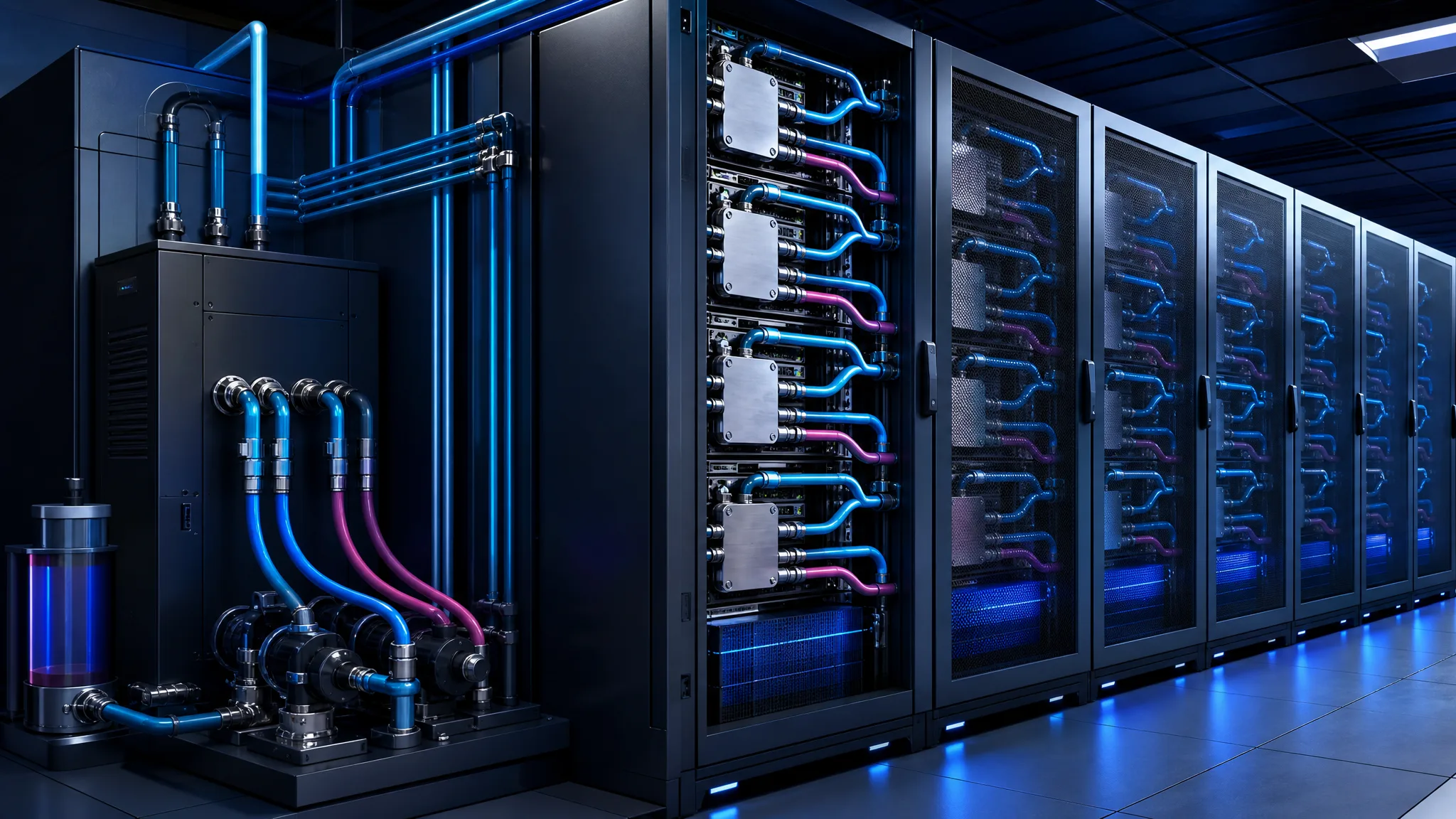
A high-density rack can pass its first power-on test and still be a poor production system. The processors may remain within their thermal limits, yet a technician may be unable to reach a quick-disconnect without disturbing cables. A leak sensor may raise an alarm without triggering a useful protective action. A second coolant distribution unit may exist on the floor, but both units may depend on the same pump, control path or isolation valve.
These are not edge cases. They are the practical questions that determine whether direct liquid cooling is ready for a working data center.
As processor, memory and rack power increase, air alone becomes harder to use efficiently for some deployments. Direct liquid cooling brings the fluid close to the heat source, usually through cold plates attached to processors or other high-power components. That can improve the path between the chip and the heat-rejection system. It also introduces pumps, manifolds, hoses, connectors, sensors, fluid-quality requirements and new maintenance procedures.
The right evaluation therefore starts with the whole chain. Can the system hold a stable temperature and flow? Can it prevent, detect and contain a leak? Can an operator service a server or a cooling component without creating unnecessary downtime? Does the redundancy work under real maintenance conditions? And can the design coexist with a room that was originally built for air cooling?
Start with the cooling boundaries
Most direct liquid cooling designs contain at least two connected but distinct circuits. The facility side carries heat away through the building’s water infrastructure. The technology side circulates coolant through the equipment. A coolant distribution unit, or CDU, sits between them.
The terminology varies by architecture, but the boundary matters more than the label. On the facility side, the data center must provide suitable capacity, connections and operating conditions. On the technology side, the cooling system must deliver a controlled fluid to the racks and return it after it has absorbed heat. The CDU transfers heat between these paths while managing conditions such as temperature, pressure, flow and filtration.
This separation gives operators a useful degree of control. The fluid moving through servers can be selected, filtered and monitored for the equipment’s requirements rather than treated as an undifferentiated extension of the building loop. It also makes responsibilities clearer—at least if the design documents state them clearly.
That last condition is easy to overlook. A leak can occur in the facility connection, inside the CDU, at a rack manifold, in a hose, at a quick-disconnect or on a server cold plate. Different teams may own each section. If the boundary between those teams is vague, the technical response becomes vague too. Who closes the valve? Who isolates the rack? Who decides whether a server should shut down? Who owns fluid replenishment and contamination checks?
Before selecting components, draw the two circuits and mark every interface. For each part, document:
- its operating role: heat transfer, distribution, isolation, filtration, measurement or control;
- its normal conditions: temperature, pressure, flow and fluid requirements;
- its isolation points: which valves or connectors allow the part to be removed;
- its failure effect: local alarm, reduced capacity, rack shutdown or facility-level impact;
- its owner: the team responsible for operation, inspection and repair.
This exercise often reveals that the largest risk is not the cold plate itself. It may be an unmonitored transition between systems, a shared power source or a valve that cannot be reached when the rack is fully populated.
In plain language
Direct liquid cooling should be designed as a complete infrastructure chain, from the facility water loop to the technology loop, CDU, manifolds, hoses and cold plates.
Judge the cold plate as part of a loop
A cold plate is the visible thermal interface between the liquid and the component. Inside it, channels carry fluid across a surface connected to the heat source. Some designs use narrow or microchannel passages to improve heat transfer. That can be effective, but it raises the importance of fluid cleanliness, pressure drop and manufacturing quality.
The advertised thermal capacity is only one measurement. A production review should ask how the plate performs at the inlet temperature and flow range that the rest of the system can actually provide. A plate that transfers heat well at a high flow rate may impose a pressure drop that forces the pumps to work harder or reduces the margin available to other branches.
Pressure drop is the resistance the fluid encounters as it moves through a component. In a rack with several cold plates, hoses and connectors, those resistances accumulate. The result affects pump selection, branch balancing and the amount of flow available at each server. A design that looks adequate when considered one component at a time can become uneven when every branch is connected.
The cold plate also has to match the fluid and the rest of the materials. Metals, seals, hoses, fittings and additives form one chemical system. An incompatible combination can contribute to corrosion, contamination or seal degradation over time. The question is not whether a plate works in isolation, but whether it remains compatible with the selected coolant and the operating conditions of the complete technology loop.
A useful supplier comparison should therefore include a matrix covering:
- thermal performance: inlet temperature, heat load, required flow and available margin;
- hydraulics: pressure drop across the expected operating range;
- fluid quality: filtration, particle tolerance, flushing and cleanliness requirements;
- materials: compatibility with coolant, tubing, connectors and seals;
- serviceability: replacement method, handling requirements and post-service checks.
Testing remains necessary. The matrix simply prevents teams from comparing products on a single thermal number while ignoring the constraints that will govern daily operation. Open Compute Project work on cold plates and related serviceability practices is useful here because it treats the cooling assembly as part of an equipment ecosystem rather than as a standalone heat exchanger.
The design should also account for loads beyond the main processor. Depending on the platform, memory, accelerators or other high-power components may require liquid cooling, while storage, power conversion and other elements continue to release heat into the room. The cold plate can reduce the dominant heat path without eliminating the rest of the thermal budget.
Make the CDU a serviceable control point
The CDU is more than a pump cabinet. It is the point where the technology loop is managed and connected to the facility’s heat-rejection capacity. Its placement, pump arrangement, filtration, telemetry and replaceable parts can determine whether a high-density deployment is practical to operate.
A CDU should expose the information needed to understand the loop: supply and return temperatures, pressure, flow, pump state, alarms and relevant fluid conditions. Telemetry does not replace physical inspection, but it gives operators a way to see drift before it becomes a thermal event. A gradual reduction in flow, for example, may indicate a filter restriction, a pump problem or an imbalance between branches.
Filtration deserves particular attention. Narrow channels and precision connectors have less tolerance for particles than a broad facility pipe. The design should define where filtration occurs, how filters are monitored, how they are replaced and what happens to the loop during that work. A filter that protects the cold plates but cannot be serviced without shutting down the entire cooling path is only a partial solution.
Placement affects both retrofit cost and maintenance time. A CDU installed too far from the rack row may require longer pipe runs, more floor space and more difficult routing. One placed in an accessible location may simplify service but compete with electrical equipment, walkways or future rack positions. The decision should be made using the actual service envelope: doors open, equipment removed, hoses disconnected and technicians working with protective equipment.
Field-replaceable units can improve maintainability, but only when the surrounding design supports replacement. The part needs isolation valves, safe drainage or containment, electrical access, lifting or handling provisions and a documented return-to-service test. A theoretically replaceable pump that sits behind fixed pipework is not operationally replaceable.
The CDU should also be evaluated against the facility loop’s future capacity. A room may have sufficient electrical power for the servers while lacking the water-side capacity to absorb their heat. The building connection, pumps, heat exchangers and control systems must be reviewed at the same time as the rack design. Otherwise, the rack becomes a local solution constrained by a remote bottleneck.
A cold plate must be assessed for thermal performance, flow requirements, pressure drop, fluid compatibility, cleanliness and replacement procedures.
Design manifolds and connectors for real maintenance
The rack manifold distributes coolant to several equipment branches and collects the return flow. It is where hydraulic balance meets the physical reality of a populated rack.
Branch balance matters because servers do not always draw the same power. If the manifold or its control method gives one branch more favorable conditions than another, some cold plates may receive less flow precisely when their thermal margin is needed. The design should consider the combined pressure drop of cold plates, hoses, connectors and the manifold, along with changes in load across the rack.
Access is equally important. A manifold hidden behind equipment or positioned where cables must be moved before every intervention turns a manageable task into a disruption. Operators need to reach isolation valves and quick-disconnects, remove a server without excessive force on hoses and see enough of the assembly to confirm that it is correctly reconnected.
Quick-disconnects designed to shut off flow at both ends can reduce the amount of coolant released when a server is removed. Blind-mate or universal connector approaches can simplify rack integration when the mechanical and service requirements are properly defined. They do not make a connection risk-free, however. A disconnect still needs a controlled procedure, inspection for damage or contamination and a verification step after reconnection.
That verification should be explicit. After a branch is serviced, does the loop need to be purged? How is trapped air detected? Is the branch pressure checked before the server is powered? Does the management system confirm that flow has returned to its expected range? These questions belong in the maintenance runbook and in acceptance testing, not in an operator’s memory.
Clean installation practices are part of the same system. Hose ends should be protected during transport and installation. The loop should be flushed according to the design requirements. Filters and fluid condition should be checked before high-value compute equipment is introduced. A particle that blocks a narrow channel may appear later as a mysterious thermal imbalance rather than as an obvious installation error.
Turn leak detection into a response system
Leak detection is often described as a sensor problem. In production, it is a response problem.
A sensor must detect an event at the right location, send a clear signal to the management layer and contribute to an action that limits damage. Depending on the architecture and the location, that action might include a local alarm, an equipment shutdown, a branch isolation or an interruption of flow. The appropriate response should be defined before deployment, because shutting down an entire rack is very different from isolating one serviceable branch.
Detection points should reflect the physical path of the coolant. A sensor near a server may identify a local hose or connector problem. Monitoring around the manifold can provide another layer. The CDU and facility interface need their own protections. No single sensor sees every failure mode, and placing sensors only where they are easy to install can leave the most consequential interfaces unmonitored.
Management integration is essential. NVIDIA administration documentation illustrates the operational direction: leak conditions need to appear in the system’s management software and connect to protective fail-safe behavior. The exact action depends on the platform, but an alarm that remains isolated in a device panel is difficult to use during a time-sensitive event.
False alarms need equal attention. Condensation, installation residue, a damaged cable or an incorrectly configured threshold can produce signals that do not represent a liquid leak. Excessive false positives teach operators to ignore warnings. A permissive threshold delays the response to a real event. Multiple sensors, environmental monitoring and a defined confirmation logic can improve the balance, but the logic must be tested rather than assumed.
A complete test should inject a controlled event and verify the entire chain:
- the sensor detects the condition;
- the signal reaches the expected management software;
- the defined protective action occurs;
- the affected section is isolated or shut down as intended;
- operators receive enough information to identify the location;
- the system can be inspected, reset and returned to service safely.
The test should also cover a failed or unavailable sensor and contradictory signals from redundant sensors. Protection that works only when every instrument is healthy is not a complete operational design.
What to keep in mind
Leak detection is only useful when it feeds a tested response that reaches management software and protective controls.
Test redundancy under maintenance conditions
Adding a second CDU, pump or loop can improve resilience. It can also create false confidence.
N+1 means that the design includes one more unit than the number required for the planned load. A two-unit arrangement, for example, may allow one unit to support the load while the other is unavailable. But that benefit exists only if the remaining path has enough capacity and the failed or maintained unit can be isolated without taking down a shared dependency.
Concurrent maintainability is the more useful test. Can a technician remove the primary cooling component while the intended workload continues? Can the remaining pumps deliver the required flow? Are the power supplies, controls, valves and monitoring paths independent enough? Is there a common manifold, pipe section or facility connection that defeats the apparent separation?
A design can contain two CDUs and still have a single point of failure. Both may depend on one electrical panel, one controller, one facility pump or one non-isolatable pipe section. The drawing may show redundancy while the operating procedure reveals dependence.
For every planned maintenance or failure scenario, document:
- which component is unavailable;
- which valves and controls isolate it;
- what flow and temperature the remaining path must deliver;
- which alarms are expected during the transition;
- who performs the change and who confirms the result;
- how the system returns to normal operation.
Manual transfer is not automatically unacceptable. It becomes a risk when it is undocumented, rarely practiced or dependent on one person’s experience. Operators should rehearse the sequence with the rack populated and the surrounding electrical and network equipment in place.
Redundancy also consumes resources. Extra CDUs, pumps and pipework require floor area, power, controls and maintenance access. The choice between N+1 and a more separated arrangement should follow the required availability and the consequences of interruption, not a generic preference for more equipment.
Plan the air and liquid retrofit together
Introducing a few liquid-cooled racks into an air-cooled room can be a sensible transition. It is not a matter of placing new racks in an existing row and connecting water.
Direct liquid cooling removes a large share of the heat from the most demanding components, but it does not remove every air-side load. Power supplies, storage, networking equipment and other components may continue to reject heat into the room. AI reference architectures commonly combine direct liquid cooling with residual air cooling for this reason. The room’s air system still needs to handle what the liquid loop does not.
Network racks deserve special attention. They may not use the same liquid-cooling configuration as compute racks, yet they can remain significant contributors to room heat and may have different airflow and service requirements. A retrofit that sizes the air system only around the liquid-cooled servers can leave the surrounding equipment without adequate support.
Space is another constraint. CDUs, pipe runs, valves and service zones compete with racks, electrical distribution and walkways. The layout must be checked with doors open, servers extended, hoses disconnected and technicians positioned where they actually need to work. Clearances shown on a simplified plan may disappear once cable bundles, power whips and containment are installed.
The electrical review must include the cooling infrastructure itself. Pumps, controls and CDUs add loads and may require separate power paths if the availability target demands them. A room can have enough capacity for the compute load but not enough for the complete cooling system, or it can have sufficient power while lacking a practical water-side connection.
Facility interfaces should be mapped before equipment is ordered. The team needs to understand where the facility loop connects, how the technology loop is isolated, which fluid each side uses, how pressure and temperature are controlled and who responds to a problem at the boundary. The organizational boundary matters as much as the pipe boundary.
A retrofit assessment should therefore begin with the existing room:
- air-cooling capacity and remaining headroom;
- residual heat from compute, power and networking equipment;
- available electrical capacity and independent power paths;
- floor loading, CDU locations and pipe routes;
- maintenance clearances and equipment removal paths;
- facility water capacity, connection points and operating limits.
Only after this map exists should the team finalize the rack and CDU configuration. Liquid cooling is a new technical distribution system. It must coexist with the old one rather than quietly replacing one part of it.
Validate the system before production loads
Commissioning should demonstrate more than the absence of a visible leak. The objective is to prove that the system can deliver its required thermal and hydraulic performance, detect abnormal conditions and support maintenance under realistic conditions.
Begin with identification and cleanliness. Confirm every branch, valve, connector and sensor against the design documents. Verify the filtration arrangement and the condition of the fluid. Inspect protected hose ends and connection surfaces. The aim is to avoid introducing contamination that later appears as a restricted branch or unstable temperature.
Next, measure hydraulic behavior by branch. A global CDU reading can look normal while one rack branch receives inadequate flow. Record supply and return conditions, branch flow, pressure drop and pump state across representative operating points. Compare the results with the cold-plate and manifold requirements, not just with a nominal system value.
Thermal testing should include changes in load. Check supply and return temperatures, control stability and the margin above the room’s dew point. The dew point is the temperature at which moisture in the air can begin to condense on a colder surface. Keeping coolant and exposed surfaces appropriately above that threshold reduces a risk that is often mistaken for a simple cooling-performance issue.
Then test the protection chain. Create a controlled leak or sensor event, confirm that the management system receives it and verify the intended protective behavior. Repeat the test with a sensor unavailable, a communication path interrupted or a conflicting signal present. The objective is not to prove that an alarm exists; it is to prove that the system reaches a safe and understandable state.
Finally, conduct maintenance drills with the actual installation. Remove a server. Operate the quick-disconnect. Isolate a branch. Replace a filter or serviceable CDU component. Transfer the load to the redundant path. Check the loop for trapped air, confirm flow and complete the return-to-service procedure. Record the time, tools, access limitations and unexpected dependencies.
A production-readiness review can then ask five direct questions:
- Are temperature, pressure and flow visible at the points needed to diagnose a problem?
- Can the system detect and contain a leak rather than merely report one?
- Can technicians service the rack and cooling equipment with the rack populated?
- Does the redundant path work during planned maintenance and an overlapping fault?
- Can the original air-cooled room support the residual heat and the added cooling infrastructure?
If any answer depends on an undocumented assumption, the design is not finished.
Conclusion: from thermal accessory to critical subsystem
Direct liquid cooling becomes valuable when rack density pushes air cooling beyond a practical operating range. But the cold plate is only the point where heat enters the liquid. Reliability depends on everything around it: the separated facility and technology circuits, the CDU, filtration, pumps, manifolds, connectors, sensors, control software, power paths and maintenance procedures.
The most useful design perspective is operational. Ask what happens when flow falls, a connector must be removed, a sensor reports liquid, a CDU is unavailable or an air-cooled room must absorb the remaining heat. These scenarios reveal weaknesses that a component datasheet cannot show.
A production-ready system is not necessarily the one with the highest advertised thermal capacity or the largest number of redundant units. It is the one that gives operators measurable conditions, clear ownership, accessible isolation points and a practiced way to maintain each part without creating a larger incident.
For new facilities, that means preserving liquid-cooling capability in the architectural plan. For retrofits, it means treating the liquid loop, the air system and the facility interfaces as one coordinated engineering problem. In both cases, direct liquid cooling succeeds when it is designed as infrastructure—not attached as an accessory after the rack has already been specified.
Sources
- Emergence and Expansion of Liquid Cooling in Mainstream Data Centers — ASHRAE
- Cooling Environments/Cold Plate — Open Compute Project
- NVIDIA DGX SuperPOD: Next Generation Scalable Infrastructure for AI Leadership Reference Architecture Featuring NVDIA DGX GB200 — NVIDIA
- System Cooling Design Overview — NVIDIA
- NVIDIA Mission Control Software with NVIDIA GB200 NVL72 Systems Administration Guide — NVIDIA
- Impacts of Introducing Liquid Cooling into Data Center Infrastructure (Presented by EdgeConneX) EXS74208 — NVIDIA
Daymain Team